Femur-ACL-Tibia Tutorial
This tutorial illustrates how to use aevaSlicer to create segmentations
by listing the steps required to segment a femur, ACL, and tibia starting
with an MRI image.
The MRI image used in this tutorial is available from the OpenKnee repository
Specifically, we use the oks014 dataset’s cartilage image (98 MiB)
named 1.3.12.2.1107.5.2.19.45406.2018071814545560005408452.0.0.0.nii.
Load an MRI image into aevaSlicer
Open aevaSlicer
File→Add Data. Select the MRI image (.nii). Select OK
In aevaSlicer, segment the femur, tibia, and ACL
Select the home module from the drop down menu. This home screen provides quick access to the data, segment editor, Surface Meshing, and Volumetric Meshing modules.
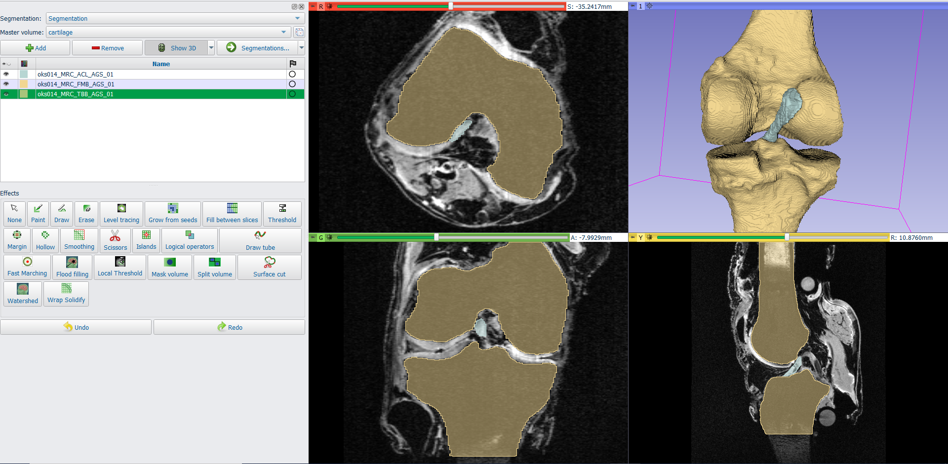
Navigate to the Segment Editor Tab. Select the desired MRI as the Master Volume.
Use the +Add button to create a new segmentation, and use the segmentation tools to delineate the anatomy.
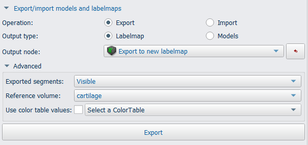
To save the segmentations, click on →Segmentations…, and then scroll down and expand the export/import models and labelmaps section. Select the Export operation. Select the output node, or export to new labelmap, and click Export below.
TIP: If you are working with multiple segmentations, default settings will save them all in the same labelamp. To save each segmnetation individually, expand the Advanced options, and select Visible from the Exported segments drop down menu. Then, toggle the visibility of all other segments from the list above.
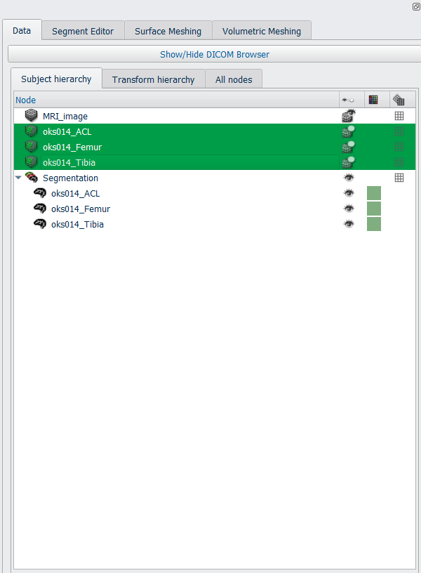
Once the export operation is complete, the exported labelmap/s will appear as nodes in the data module.
Use File->Save to save the segmentations. Select the check box next to the files you would like to save, and change file format (.nii) and directory.
You may continue to edit these segmentations at a later time by loading them into Aeva Slicer (Add Data), and importing to the segment editor. When using Add Data, check the “show options” check box on the upper right hand side, and make sure that the “Labelmap” checkbox is selected, so that the segmentations will be imported correctly.
Note than any changes made in the segment editor are not automatically applied to the data nodes. The changed labelmaps must be exported to the data nodes in order to be able to save the changes.
In aevaSlicer, generate the femur, tibia, and ACL surfaces
Import the completed segmentations into the Segment Editor, if they are not already there.
From the home module, navigate to the Surface Meshing tab. Under the input segmentation, select “Segmentation” (or the name of the current working segmentation in the segment editor)
To generate triangulated surfaces from the segmentations, select “Export Visible Segments to Surface Models”. Default settings will generate triangulated surfaces without smoothing. Use the “smooth models” checkbox and slider for automatic surface smoothing.
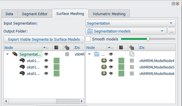
The left panel will display the labelmaps in the Segment Editor. The right panel will display the generated triangulated surfaces.
On the right side of the screen, the Data module will be displayed. This provides easy access to toggle visibility, and change properties of the visible meshes. When a mesh is selected on the data list, properties options will appear below.
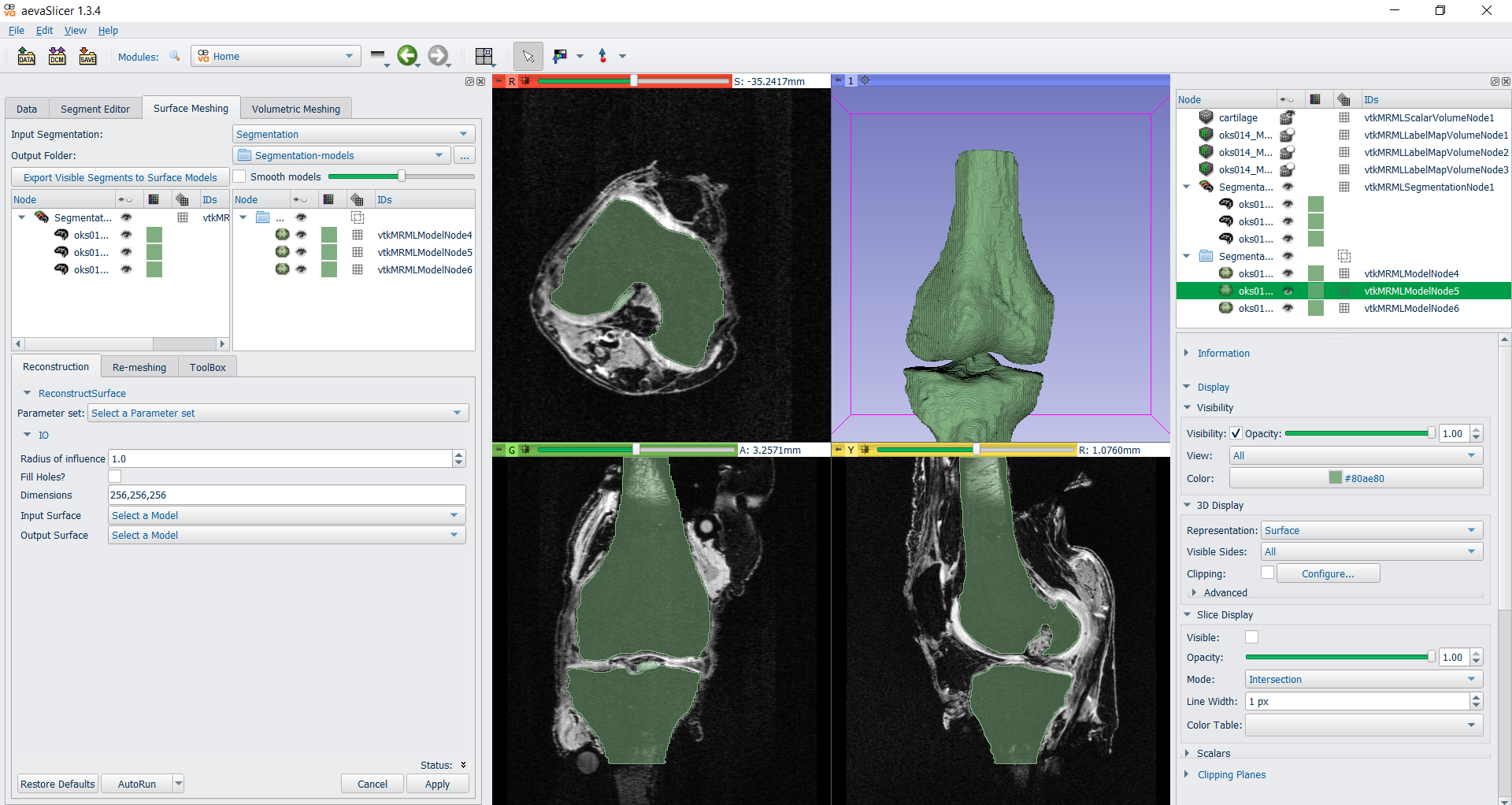
On the lower half of the left hand side, there are three tabs with mesh operations. Reconstruction, Re-meshing, and Toolbox. These tools can be applied to an existing surface mesh. Once the segmentations have been exported to Surface Meshes, these operations may be used for further smoothing, decimation, re-meshing, etc. Operations may be performed in any order.
For this tutorial, the models will be exported with automated smoothing, followed by re-meshing to reduce the density of the surface meshes.
First, export segments to surface models, with maximum automated smoothing, using checkbox and slider as described above.
Select each of the meshes on the data list, and change the color to one that is different than the segmentations. Under slice display, check the “visible” box. This will display the outline of the surface mesh on the slice. This can allow for the user to assess if any volume was lost from the segmentation during smoothing. If this is the case, adjustments can be made to the level of smoothing.
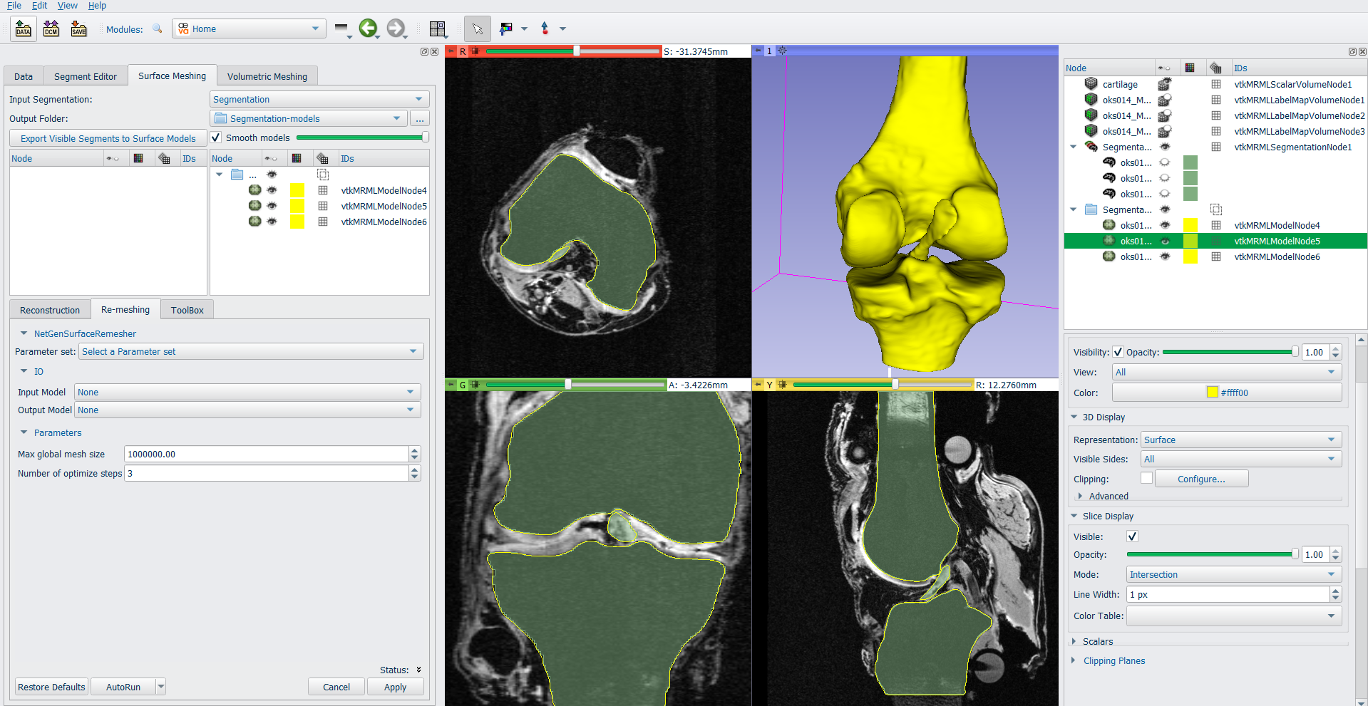
Navigate to the Re-meshing tab on the lower left side of the screen. Under parameter set, select Create new parameter set. Select the input model, and an output node for the resulting surface mesh (create new model as..). Set the max global mesh size to 1. Select Apply. Repeat this process for each of the tissues, and adjust mesh size as needed. Use the data panel to select each mesh and change the 3D display to Surface with Edges to view the mesh outline.
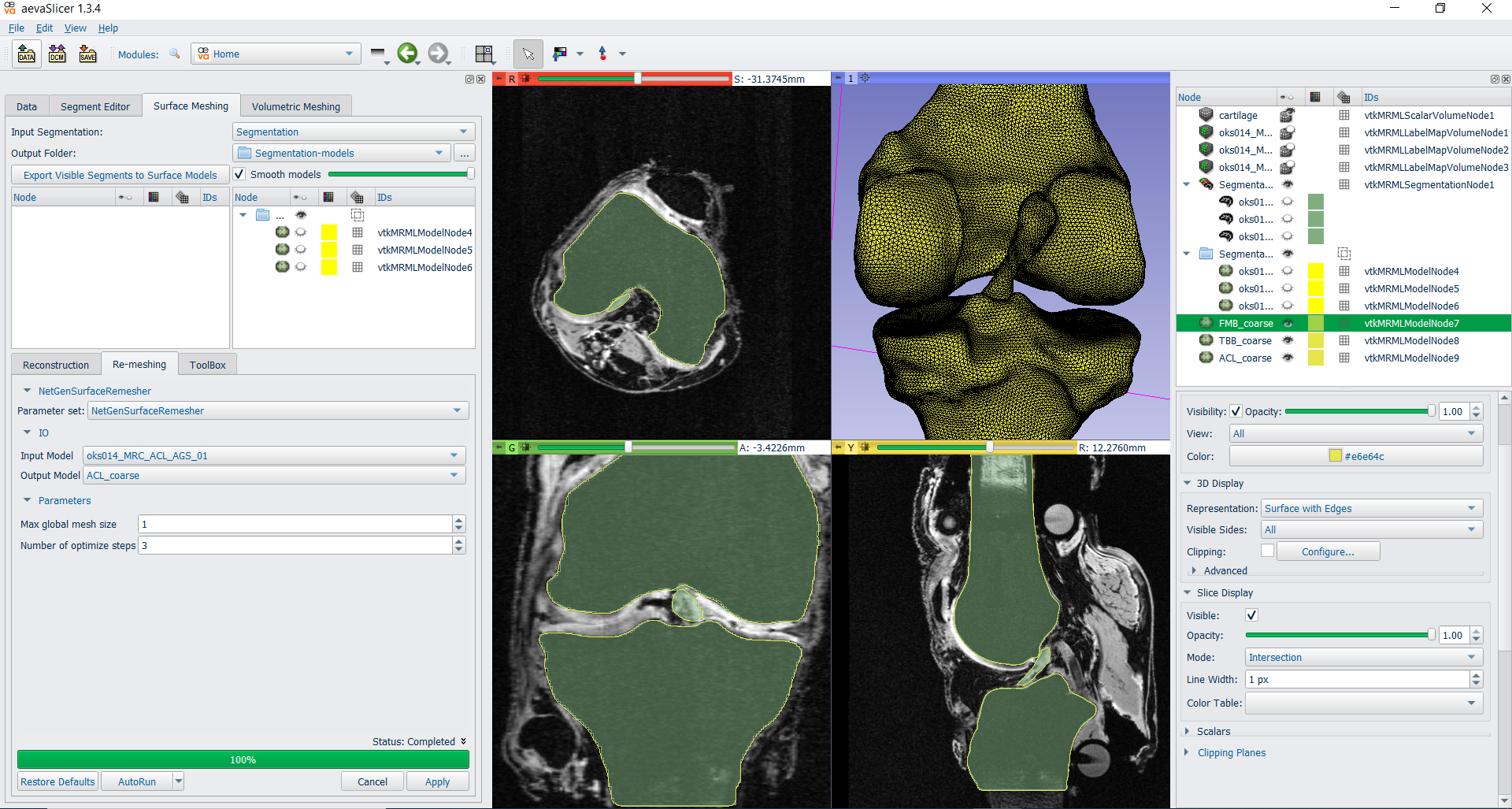
To Save the Surface meshes (File→Save). Surface meshes that were created using “Export visible segments to surface models” will appear in the list with the same name as the segmentations, but with a Poly Data (.vtk) extension. Change the name, file format (.stl), and destination directory if desired.
In aevaSlicer, generate the volume mesh for ACL
For this case study, only the ACL model will have a volumetric mesh, as the bones will be modeled as rigid bodies and can remain as surface meshes.
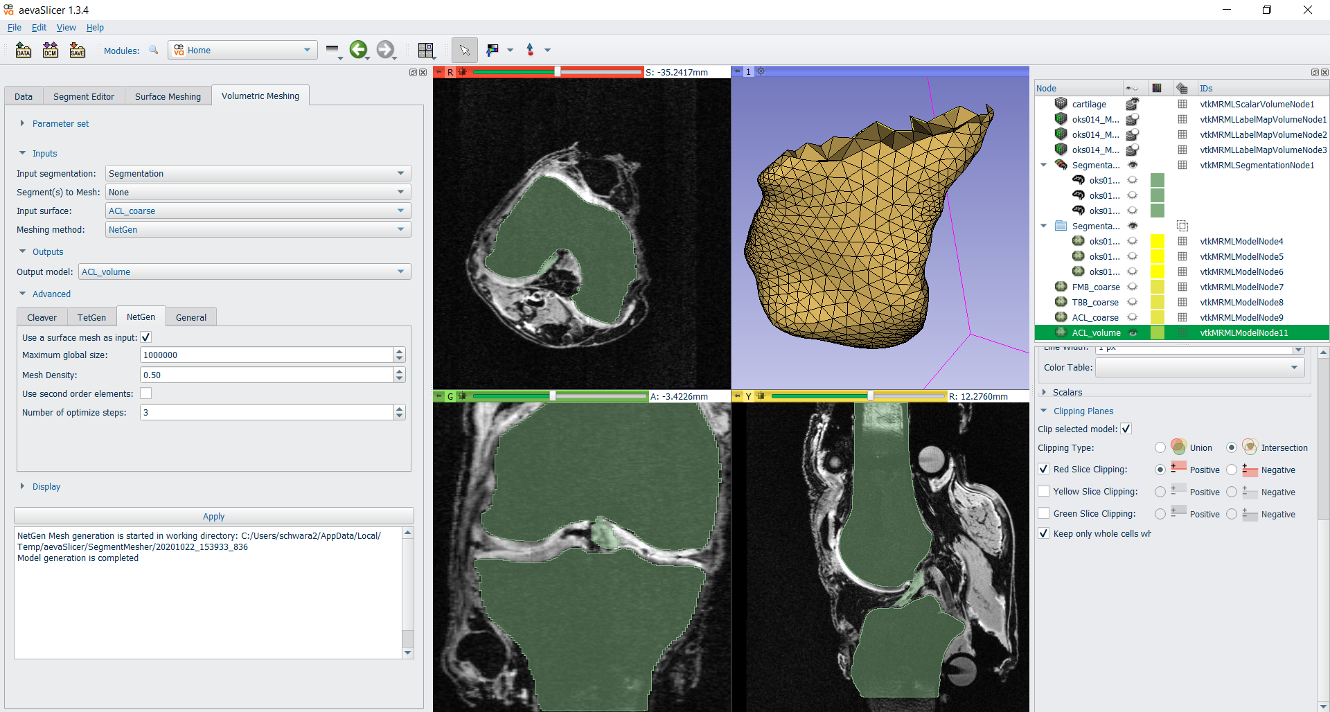
From the home module, select the Volumetric Meshing tab.
Select the input. To use a previously generated surface mesh, first select the Meshing method as NetGen. Then, under Advanced, Select the NetGen tab, and click the “Use surface mesh as input” check box. Now you may select the input surface from the drop down menu above.
Select the ACL surface mesh from the drop down menu. For the output node, “create new model as…” . Select Apply.
Using the data panel on the right hand side of the screen, display settings can be adjusted to visually inspect the mesh. Select the mesh from the data list. Under 3D display, set the representation to “surface with edges”. Under clipping planes, check the box for “clip selected model” choose the slice along which you wish to clip, and check the box for “keep only whole cells when clipping”. You may then scroll through the slices to move the clipping plane through the mesh.
Save the mesh as a Poly Data file (.vtk) using File→Save
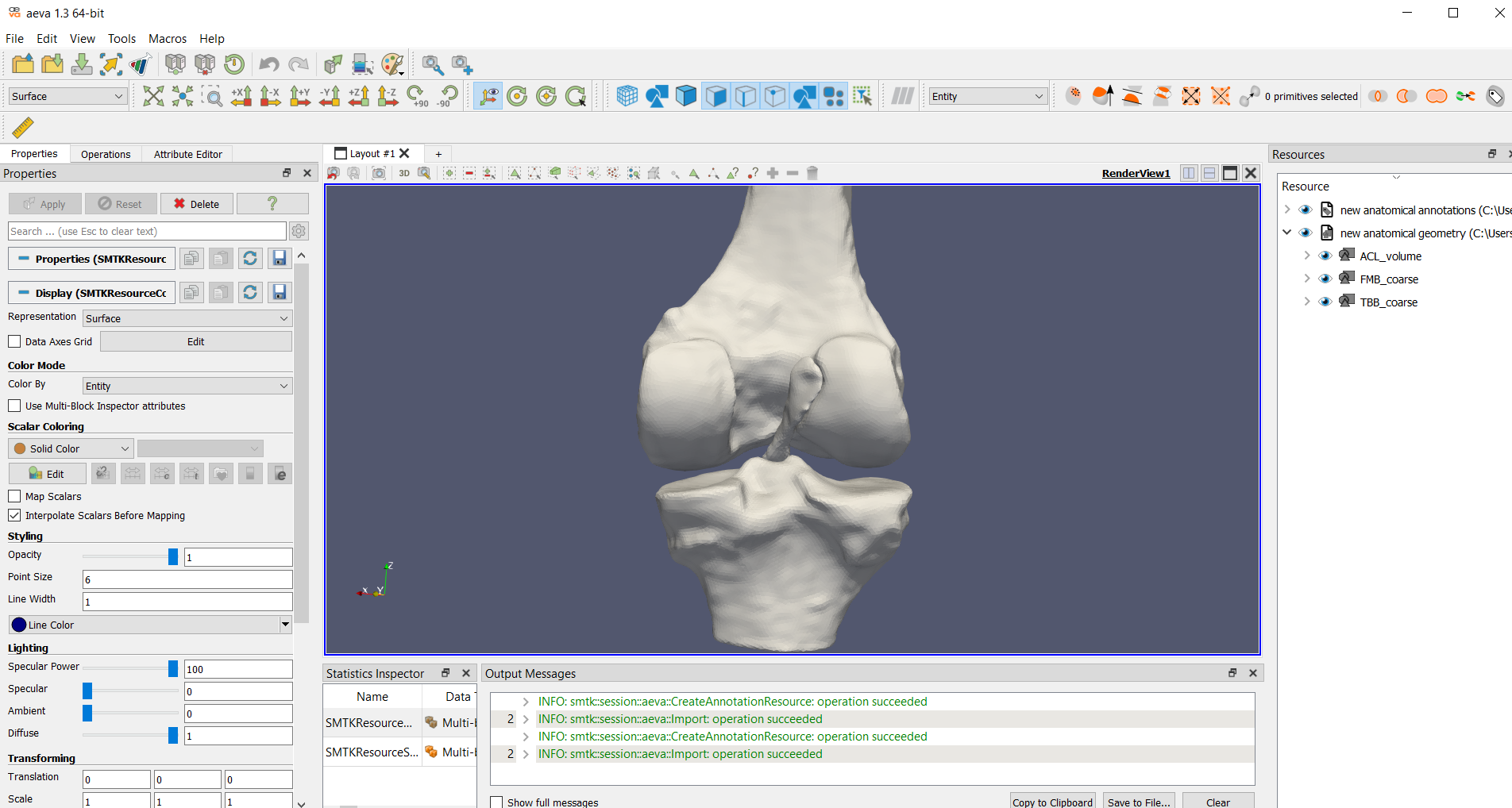
In aevaCMB, load the meshes
File->New Resource->Aeva annotation resource
From the resource tree, select the “new anatomical geometry“ resource, then File->Import into resource.
Select the bone stl files, and the ACL vtk file. Select OK
Note: These files may also be opened individually, using File->Open. However, it is recommended to import all the meshes into one geometry resource in order to more easily save your work in aevaCMB.
In aevaCMB, define face and node sets
Several different selection tools are available for creating groups of element or node sets to define insertion areas.
Manual Selection
On the panel above the RenderView screen, manual selection tools are available. “Select cells with polygon” is recommended for selecting irregular shapes. Simply click and drag to select the desired region. Once a region has been selected, use the + or – buttons to add or subtract from the existing set. See directions below for saving the sets. Saved selections may also be edited by selecting the set from the resource tree, followed by + and -, and the desired selection tool.
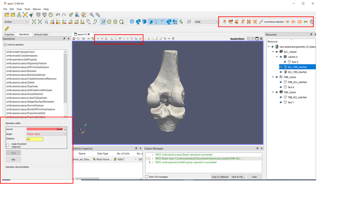
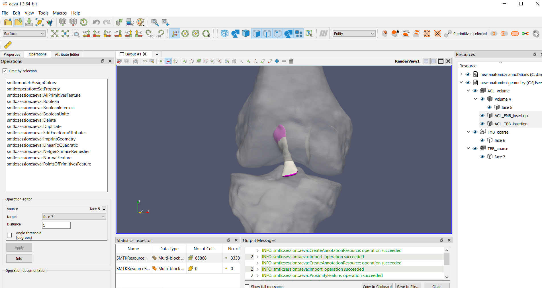
Automated Selection
On far right side of the panel at the top of the aevaCMB window, several automated selection tools are available. Choose the desired selection tool. In the operations taskbar, under Operation Editor, select the source and target face (expand the resource tree to see which faces belong to which geometries). The selection will be created on the source mesh, and the target mesh will be used as the tool.
Converting element sets to node sets
On far right side of the panel at the top of the aevaCMB window, “Select the nodes of all selected primitives” will create a selection of all nodes of the currently selected elements.
Saving Selections
Once a set is defined as desired, select “Duplicate Cells” on the upper right. This will create a new group under the geometry in the resource tree, called “copy of selection”. Double click on the group to rename it as desired.
In aevaCMB, save the resource as smtk
Select the entire geometry resource (new anatomical geometry), and select File->Save Resource As.
Save the smtk resource. This smtk file may be easily re-opened in aevaCMB for further editing using File->Open